SUB-ASSEMBLY DESIGNS
Product assembled with matching gear reducers and tested as a packaged product. This includes worm gear reducers and all types of mating drive technology. Additionally we provide sensor technology, inductive, capacitive, or analog/digital. Enclosures are available in metal or plastic for any environment.
A typical electric drive system includes a controller, a transmission, an electric motor and a driven load, an example would be: fans, pumps, conveyors door openers and others. A key difference in different types of electric drive systems is the type of controller: Distinct D.C. motor control components, such as motor starters, switches and operator controls, or electronic motor controllers, called drive controls, that use semiconductors with electronic circuitry and software to perform the same functions of distinct D.C. motor control components.
A GUIDE TO DC DRIVES AND MOTOR CONTROL
Controlling the motion and the processes of different machines and mechanisms.
An electric drive is an electromechanical system that employs an electric motor as the prime mover. Typical applications of electric drives include fans, ventilators, compressor pumps, hoists, cranes, conveyors, excavators, escalators, electric locomotives and cars and increasingly, consumer appliances. An electric drive has several advantages over other types of drives systems, such as:
▪ Control characteristics can be adapted to application requirements.
▪ Simple and easy speed control methods
▪ Electric braking can be applied easily
▪ Pollution free
▪ Wide range of speed, power and torque ratings
▪ Efficiency is higher
▪ Short time overload capacity
▪ Function a variety of work environments, such as submerged
▪ Self-starting–no need of external starting equipment
▪ By comparison its operation is less noisy with less maintenance
> BACK
TYPES OF DC MOTOR CONTROL
There are three general types of D.C. motor control: manual, semi-automatic and automatic.
(1) Manual control directly connects a D.C. motor to the input power line or mains. You or someone else is required for operation. Semi-automatic control uses switches or sensors to limit or pressure or temperature, float level, flow, proximity, timing and photosensitive switches. This is to control a magnetic contactor or starter which, when enabled or closed and will connect the motor to the input power line.
(2) In semi-automatic operation, an operator is needed to start or stop the motor but the sensors or switches control the rest of the operation.
(3) Automatic control is similar to semi-automatic control with one important difference: no operator intervention is required. For example, a thermostat in an air conditioning system or a refrigerator will turn a compressor motor on or off to maintain the set point temperature automatically.
FUNCTIONS OF DC MOTOR CONTROL
Whether a D.C. motor is controlled manually, semi-automatically or automatically, the control system will perform a variety of common functions:
STARTING
There are several types of starting functions. Across-the-line starting is the most basic starting method. The motor is connected directly to the power line via an operator control switch. Closing the switch connects the motor to the line. However, for some D.C. motor types, applying full voltage line during starting would generate huge amounts of inrush current, which could be beyond the capacity of the power supply as well as possibly cause damage to the motor. In these cases, a starting resistance is used to limit the inrush current. This is accomplished by temporarily inserting a starting resistor in series with the motor’s armature winding. The resistor drops some of the line voltage to limit the starting current. The motor will gradually accelerate; this is commonly called soft starting. When the motor comes up to full speed, the starting resistor is removed.
STOPPING
There are three forms of stopping: coasting, braking or a deceleration ramp. When power is removed from a motor, it begins to coast to a stop and is time-dependent upon the inertia and the load. Coasting is not always practical and in some applications the motor would take to long to stop. In these situations, a brake can be used to stop the motor quickly. There are four types of brakes: mechanical, magnetic clutch/eddy current, dynamic and regenerative brakes. Dynamic braking is accomplished by dissipating the kinetic energy in the armature across a braking resistor. During stopping, while the armature is rotating, it acts as a generator. The dynamic braking resistor becomes this generator’s load, thus, a transfer of energy occurs from the armature (acting as a generator) into the resistor, which dissipates the energy in the form of heat, causing the motor to slow down.
JOGGING AND INCHING
Jogging/inching moves the motor very short distances for positioning or alignment purposes. Inching uses a reduced voltage to move a motor while jogging uses full voltage.
PLUGGING
Plugging has the dual function of stopping or reversing a motor. This is accomplished by reversing the supply polarity to the armature while the motor is still running. As a result, a counter torque is developed and the motor slows down quickly. When the motor reaches zero speed and begins a reverse rotation the power supply to the motor is disconnected by closing a zero speed plugging-switch.
REVERSING
Reversing controls the direction of the motor’s rotation (CW or CCW). It is accomplished through a control switch or via an electronic drive controller and entails reversing the polarity of the armature connections, which can be done with a push button control of mechanically interlocked forward and reverse buttons or programming the electronic drive controller for reverse operation.
SPEED CONTROL
A D.C. motor’s speed can be varied throughout the continuous speed range by varying the armature current by using a resistor or an electronic drive controller.
PROTECTION
Protective circuits will protect the motor with, fuses, circuit breakers, overload relays, open field protection, over speed protection, current sensors and metal oxide varistors (MOV) for surge protection.
DC DRIVES SELECTION
An electronic D.C. drive, sometimes called a semi-conductor drive, is a subset of all the various electric drive systems used to control the motion and vary the speed of a D.C. motor.
Advantages
▪ Large range of power availability.
▪ Capable of full torque at standstill without a clutch.
▪ Very large speed range without needing gearboxes.
▪ Clean operation.
▪ Safe operation in hazardous environments.
▪ Immediate use (no warm up time)
▪ Low no-load losses.
▪ Low acoustic noise.
▪ Excellent control ability.
▪ Four-quadrant operation: forward motoring, forward braking,
reverse motoring and reverse braking.
Disadvantages
▪ Are complex and require skill to maintain.
▪ Introduce harmonics/electrical noise into the power line
ELECTRONIC DC DRIVES
Control Methodology and Characteristics
An electronic D.C. drive is an electronic thyristor AC/DC converter/rectifier or a DC/DC converter, called a D.C. chopper. A converter is a complex electronic control that can precisely control a D.C. motor’s rotation, torque and speed characteristics. AC/DC converters come in several configurations: Full-wave, 12-pulse bridge or full-wave, 6-pulse bridge or half-wave, 3-pulse bridge. The most common configuration is the full-wave, 6-pulse bridge because it produces less distortion on the DC side of the converter and has lower losses in the DC motor than a 3-pulse bridge. DC motors with 12-pulse bridges are typically used on larger drives to reduce harmonics on the AC power line. The efficiency of the converter is usually greater than 98% and the overall efficiency of the D.C. drive plus the D.C. motor is about 90%. In addition, AC/DC converters can be built for applications up to several megawatts with good control and performance characteristics.
The other type of D.C. drive controller is a DC-to-DC converter.
While an AC/DC converter is powered from an A.C. supply, the D.C. chopper is powered from a D.C. power source. Both electronic controls produce a variable D.C. voltage that when applied to the D.C. motor’s armature varies the armature current, hence, the motor speed. The AC/DC converter produces this variable D.C. voltage by controlling the firing angle of its SCR bridge rectifier, while a D.C. chopper varies the voltage by controlling the varying angle to vary the duty cycle. The output voltage of the chopper is in the form of pulses. The time ratio of the chopper can be controlled to vary the average voltage. Voltage variation at the load can be obtained by either current limit or time ratio control. For instance, in current-limit control, when current reaches the upper limit, the chopper is turned off to disconnect the motor from supply. Load current freewheels through the freewheeling diode and decays. When it falls to the lower limit, the chopper is turned on and connected to supply, thus, an average current is maintained.
GEAR DRIVE-MOTOR SYSTEM
A basic element frequently overlooked when developing an efficiency strategy is the drive systems comprised of worm gear boxes coupled with an electric motor. Typically, drive components retain, or even improve, the same function. Electric drive systems are everywhere. You will find them on conveyors, air handlers, pumps, mixers, hoists, compressors, and countless other applications.
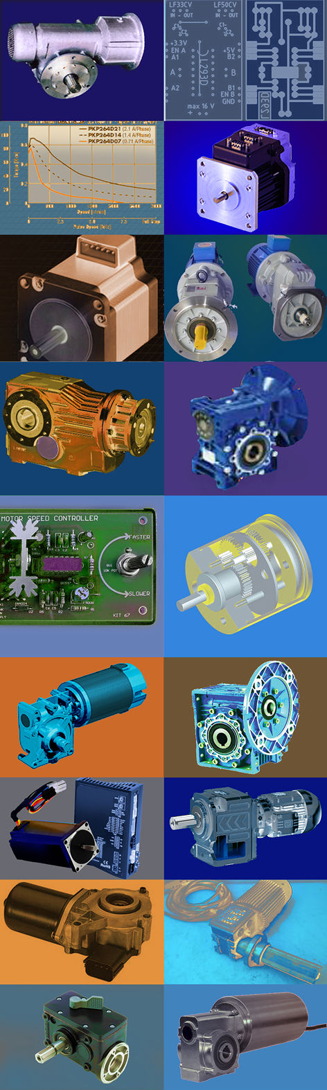
PRODUCTS
1. Gear Reducers
2. DC Brushed Motors
3. DC Brushless Motors
4. DC Brushed Controllers
5. DC Brushless Controller
6. Stepper Controllers
7. Custom Mechanical/Electrical Assemblies
INCREASE EFFICIENCY AND REDUCE POWER CONSUMPTION
With efficient engineering electric drive systems can be designed to cut energy consumption. FFI’s sub assembly designs package gear drive-motor, incorporate gearboxes and a highly efficient motor, into one modular unit. By designing components to be configured as needed, maximizing the versatility and flexibility of the drive to the application and increasing system efficiencies. The perfect-fit solution!
> BACK